Most people outside the manufacturing world assume a cast metal part starts with molten metal. In reality, it starts long before the furnace is ever fired up. The real beginning is a design file, a conversation about alloys, and a series of engineering decisions that determine whether the finished part will perform as intended or arrive with porosity, shrinkage, and a scrap bill to match. That early phase of work has a name: aluminum casting product development. It is the bridge between a concept on a screen and a repeatable, defect-free production process, and it is where most casting projects are either won or lost.
This article walks through that process step by step, from the initial CAD file to the first finished part, and explains why the engineering work that happens before the pour matters so much.
Step 1: Design Review and File Handoff
Table of Contents
Every casting project begins with the customer’s design. These days, that usually means a CAD file, though PDFs and other formats still make their way into foundry engineering departments. The first job of the product development team is not to simply accept the file and start cutting tooling. It is to study it.
Engineers examine the geometry with a specific question in mind: can this shape actually be cast in aluminum, and cast well? Walls that are too thin may not fill properly. Sections that are too thick can create shrinkage voids as the metal cools. Sharp internal corners concentrate stress and can cause tears during solidification. None of these issues are visible to the naked eye on a pretty rendering, but all of them can sink a project.
This is also the stage where the foundry and the customer talk about tolerances, surface finish expectations, and any features that will need machining after casting. A good development team flags potential problems now, while changes cost nothing, rather than after tooling has been built.
Step 2: Alloy and Material Selection
Aluminum is not one material. It is a family of alloys, each with different characteristics. Some are formulated for strength, others for corrosion resistance, others for pressure tightness or machinability. Choosing the wrong alloy is one of the fastest ways to end up with a part that meets the drawing but fails in service.
During this phase, engineers match the alloy to the product’s actual working conditions. Will the part carry structural load? Will it see high temperatures? Does it need to hold fluid without leaking? Does it weld well? These questions drive material selection, and they are answered alongside the geometry review, because alloy behavior and part shape influence each other. Mechanical properties and tensile strength targets get locked in here, and everything downstream is built to hit them.
Step 3: Process Planning and Feasibility
Before a single ingot is melted, the development team plans the production process itself. How many parts are needed, and at what cadence? What size furnace and pouring equipment does the job require? Is the part better suited to a particular molding approach? These decisions affect cost, lead time, and quality, and they are far easier to make on paper than to reverse mid-project.
This is also where a feasibility study earns its keep. A feasibility study is a structured look at whether the part can be produced to spec, at volume, at a price the market will bear. Skipping this step to save a little upfront cost is a gamble, and it is one that frequently loses. Problems discovered during feasibility are engineering notes. The same problems discovered during production are scrap.
Step 4: Simulation and Gating Design
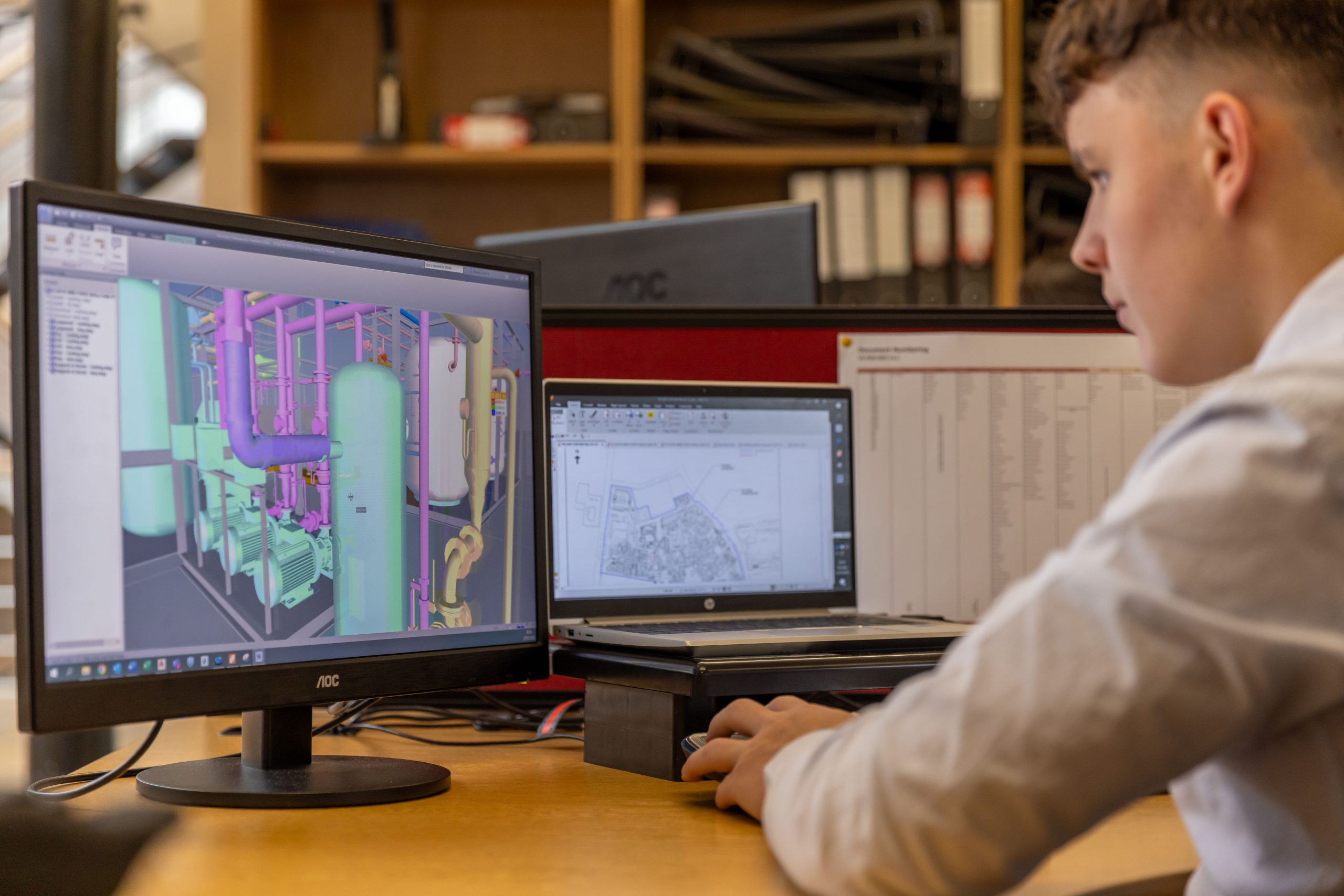
Here is where modern casting development separates itself from the old trial-and-error days. Before metal ever touches a mold, engineers can simulate the pour digitally. Solidification software models how molten aluminum will flow into the mold cavity, where it will settle, and how it will cool and hardify.
Why does that matter? Because most casting defects are predictable if you can see them coming. Shrinkage cavities form where metal cools last. Cold shuts and misruns form where metal loses heat before filling a section. Inclusions show up where flow patterns trap debris. Simulation lets engineers spot these trouble zones on a screen and design around them.
The main tool for doing that is the gating system, the network of channels that delivers metal into the mold. Gate placement, size, and angle control how fast the metal enters, how calmly it fills, and how the thermal field develops as the part solidifies. A well-engineered gating system produces consistent, defect-free castings run after run. A poorly designed one produces a parts bin full of rejects and a lot of frustrated phone calls. Getting this right in software, before tooling is committed, is one of the biggest cost and time savings in the entire development cycle.
Step 5: Prototyping and the First Pour
When the design and process are validated on screen, it is time to make something real. Traditionally this meant building pattern tooling first, which is expensive and slow when you only need one or two parts to prove the concept. That is changing.
Additive manufacturing has opened a faster path. With 3D sand printing, a foundry can print a mold directly from the digital model, no pattern required. The development team takes the 3D model, applies foundry engineering to add the gating system, and prints the mold in sand. Then they pour the prototype. What used to take weeks of pattern work can now happen in a fraction of the time.
The value goes beyond speed. Printed sand molds let engineers test real castings early, catch problems in physical form, and refine the design before committing to production tooling. For a product team on a deadline, the difference between a prototype in days versus a prototype in months can decide whether a launch date holds.
Step 6: Process Control and Documentation
The first good part is a milestone, not a finish line. The last phase of product development is making the process repeatable. That means documenting process controls: pour temperatures, mold conditions, timing, alloy handling, and inspection criteria. It means establishing the checks that catch drift before it becomes defects.
This is unglamorous work, and it is exactly what separates a foundry that can hit spec on part number one thousand from one that got lucky on part number one. Customers who depend on cast components for machinery, equipment, or repairs live and die by consistency, and consistency is built during development, not improvised during production.
Why the Upfront Work Pays Off
It is tempting to view all of this engineering as overhead, something between the customer and the parts they ordered. The opposite is true. Every dollar spent on design review, simulation, and prototyping avoids multiples of that cost in scrap, rework, tooling revisions, and missed deadlines. Defects prevented in software cost nothing. Defects discovered in the field cost the most of all.
There is a broader lesson here for anyone designing metal parts. The foundry you hand your CAD file to is not just a vendor with a furnace. The best ones operate as an engineering partner, one that can tell you why a feature will not cast well, simulate the fix, print a prototype to prove it, and document the process so production stays stable. When you evaluate casting suppliers, look past price per part and ask what happens before the pour. The answer tells you almost everything you need to know about how your project will turn out.